Half wave bridge rectifier circuit diagram Half wave and full wave precision rectifier circuit using op-amp Rectifier circuit diagram
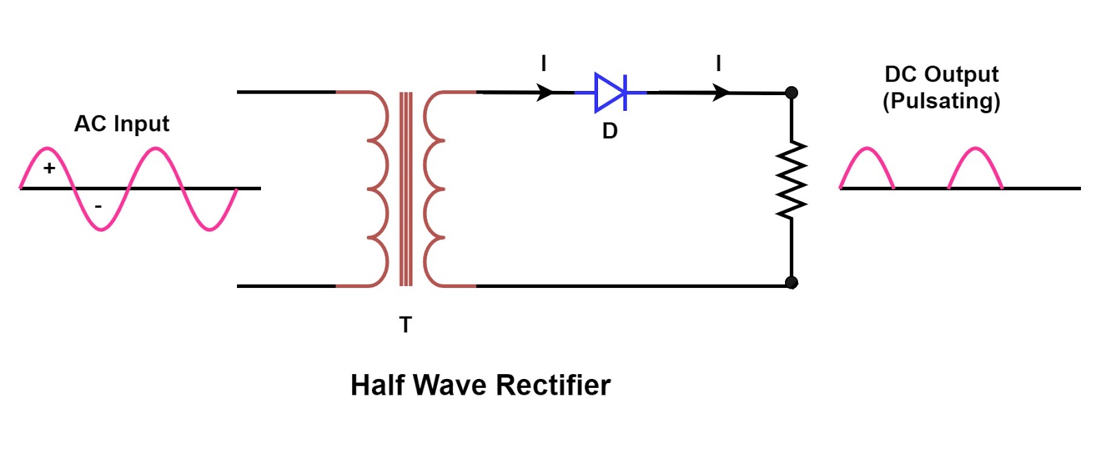
Draw the circuit diagram of a half wave rectifier and explain its working.
Wave half rectifier capacitor filter circuit diagram output full waveform rectifiers diode bridge using transformer resistor rc operation working diodes Half wave rectifier circuit diagram Half wave rectifier circuit with diagram
Solved figure 5(a) shows the circuit diagram of a half-wave
Solved figure 1(a) shows the circuit diagram of a half-waveWave rectifier half circuit diagram hwr Rectifier wave rectification diodeRectifier waveform representation.
Half wave rectifier basics circuit working amp applicationsRectifier circuit waveform input Rectifier halfwave difference byjus formulaRectifier wave half.

What is a half wave rectifier? circuit, working and waveform
Half wave rectifierHalf wave rectifier circuit working amp its characteristics Draw the circuit diagram of a half wave rectifier and explain its working.Wave half rectifier diode ac voltage supply output circuit peak inverse dc piv operation load value input when average resistance.
Half wave rectifier – definition, working, circuit diagram, theoryHalf wave rectifier(explanation) Rectifier wave diode circuitdigest breadboard diodesWhat is half wave and full wave rectifier?.

Rectifier rectification halfwave circuit waveform rectifiers transformer ripple applications physics
Half wave rectifier circuit simulation download scientific diagramHalf wave rectifier Single phase half wave rectifier- circuit diagram,theory & applicationsHalf wave rectifier.
Half-wave rectifier circuit working explanation .


Draw the circuit diagram of a half wave rectifier and explain its working.

Half Wave Rectifier – Definition, Working, Circuit Diagram, Theory

Solved Figure 1(a) shows the circuit diagram of a half-wave | Chegg.com

Half Wave and Full Wave Precision Rectifier Circuit using Op-Amp

Half Wave Rectifier Circuit with Diagram - Learn Operation & Working

Single Phase Half Wave Rectifier- Circuit Diagram,Theory & Applications
Half Wave Rectifier - Definition, Working, Formula, Applications

Half Wave Bridge Rectifier Circuit Diagram
What is a Half Wave Rectifier? Circuit, Working and Waveform